| Company | Role | Skills |
|---|---|---|
| Arup | Technology Consultant | Stakeholder Management |
| User Interviews | ||
| Requirements Gathering | ||
| System Calculations | ||
| CAD - Revit/MicroStation |
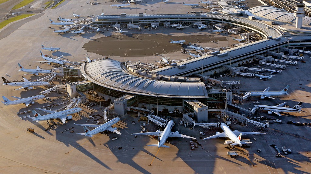
While considering client and industry constraints, I collaborated with several departments across Arup to design the public address speaker system for the Toronto Pearson Airport. To come up with the design, I considered concepts like audibility, intelligibility, sound projection cones, listening planes, installation pattern layouts, and more.
Founded in 1946 by engineer-philosopher Sir Ove Arup, the Arup Group is an independent firm of designers, planners, engineers, architects, consultants, and technical specialists. The impact of the Arup Group can be seen worldwide, from concert halls like the Sydney Opera House to the physical connections between countries. For over 7 decades, the firm has been solving the world’s most complex challenges and has been at the forefront of the most ambitious engineering endeavours.
The Digital team at Arup is responsible for digital technology systems in the built environment, including real-time crowd simulation and management, security platforms, integrated data networks to enable smart buildings, and more.
Co-op students are always given the opportunity to make meaningful contributions to real projects, and my time there was no different. I was given the opportunity to work with our largest client, the GTAA (Greater Toronto Airports Authority), as a Technology Consultant. Specifically, I was tasked with the redesign of the technology systems of Toronto Pearson Airport; one of them being the public address system.
Public address systems are electronic systems in public venues that provide crucial information to large audiences in, or near the venue. A typical public address system has several components: a speaker, cabling, an amplifier, a controller, a data network, a noise sensor, and an audio input source.
To get ahead of this overcrowding concern, the Toronto Pearson Airport has been renovating and creating new interior real estate. For these new spaces, the GTAA contracted the Arup Group to provide design, installation, and consultation services for several technology systems.
In certain settings, the quality of sound can amplify emotions. Well-designed sound systems in concert halls allow listeners to immerse themselves in the music. In sports stadiums, fans can feel closer to the action. In other cases, well-designed sound systems can save millions of lives. The clear and quick communication of urgent information is key when large masses of people are constantly flowing in and out of a building. While a speaker system may be taken for granted in most cases, it can be the difference between life or death in extreme situations. In less extreme situations, these speaker systems are still vital in conducting crowd control and minimizing stress and confusion for passengers.
Audibility refers to the ability of a sound system to be heard and is measured in decibels to indicate sound pressure levels (SPL). Audibility issues can easily and dynamically be addressed with noise sensors and amplifiers, or by increasing the wattage of a speaker.
Intelligibility, on the other hand, refers to the ability of a sound system to be understood and is measured in Speech Transmission Index (STI) values. Intelligibility is more difficult to troubleshoot since it depends on multiple factors such as ambient noises, the material and thickness of the walls, the material and placement of any furniture, or even the quality of the speakers themselves.
As sound waves travel through a medium, there’s a loss in decibel values. For ceiling-mounted speakers, when conducting calculations, we can assume a zero-decibel loss straight down from the speaker. When viewed two-dimensionally, it's also assumed that sound travels in the form of an equidistant arc. The extremities of this arc are defined as the points at which a six-decibel loss is observed. When viewing this sound projection three-dimensionally, the resulting shape is a cone of dispersion.
The listening plane is the height at which the intended audience’s ears will be most of the time. As illustrated below, the listening plane is typically at the height of a speaker’s six-decibel down points.
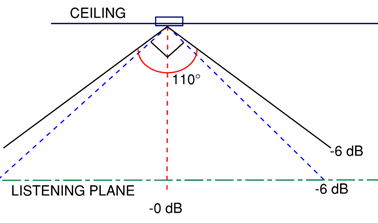
For corporate offices, the listening plane would typically be four feet from the finished floor, because everyone would be sitting for most of the day. For busy airports, the listening plane would be five feet from the finished floor, since most passengers are always on their feet. The listening plane is always based on the finished floor, rather than the structural floor because additional decorative flooring could potentially alter the behaviour of sound waves in the space.
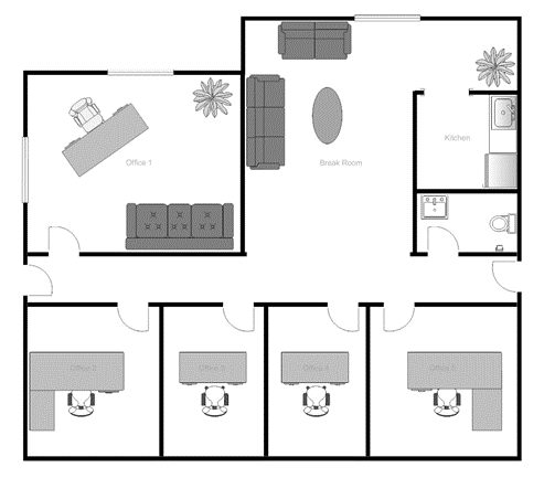
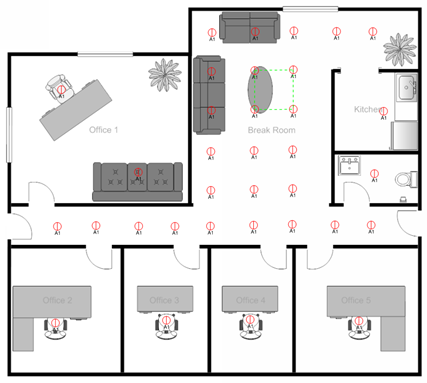
In the interest of national security, none of the construction drawings from the airport will be disclosed in this case study. However, the concepts I discuss will be illustrated using the sample office layout shown below. Based on estimations of furniture size, the office layout will be approximated to be 700 square feet, which will be important later. Since we are working with a typical office environment, all speakers illustrated will be industry-standard 4-inch diameter ceiling-mounted speakers.
There are generally two possible configurations for the speaker system layout. The first being a square pattern, as shown below on the left. The alternative, the hexagonal pattern, is shown below on the right.
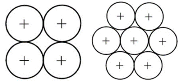
From the above, it can be seen that the hexagonal layout provides more surface area coverage, due to the minimization of the gaps between dispersion cones.
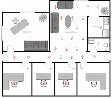
Another concept to consider when optimizing the design is that the more speakers there are in a system, the lower the wattage requirement is for each speaker. In an ideal world with an unlimited budget, there would be a speaker in every single ceiling tile with minimal wattage provided to produce the auditory illusion of one uniform sound being emitted from above. The image below depicts the two possible layout patterns given that there are no restrictions on the number of speakers that can be installed.
Something to consider when debating between a square layout pattern and a hexagonal layout pattern is the intersection of the cones of dispersion with the listening plane. If there’s a point of intersection between cones of dispersion above the listening plane, an echo occurs, which is irritating to the listener, and more importantly, unintelligible. Conversely, if there are uncovered regions, a broadcasted message could be inaudible to some. From a two-dimensional perspective, these issues are incredibly simple to address. However, in a three-dimensional environment, issues begin to arise. Due to the areas of coverage being conical rather than two-dimensional arcs, there is physically no perfect solution that allows for the absence of overlap, or uncovered regions. This decision ultimately relies on the priorities of the client.
If a client doesn’t have an opinion, a weighted decision matrix could be used to choose between the two pattern layouts. To construct the matrix, several factors of the project must be considered and weighed, as shown below. The budget of a project is very important, but it can always be altered provided there exists an absolute need, so it will be weighed highly, but not as the highest. The aesthetic appearance of the system leaves an impression on the client regarding the designer’s level of competency, so it's also important. However, in the consideration between public safety and aesthetic appearance, public safety takes priority and possesses the highest weighting. Although the most important parties to consider are the client and the users of the public space, a third party to consider is the contractor responsible for the physical installation of the system. In consideration of these contractors, the level of intricacy involved in the installation process should also be considered, but not weighed as highly as other factors. For this case study, the ideal pattern layout of the two can be determined with the following decision matrix.
| Criteria | Weight | Square | Hexagonal | ||
|---|---|---|---|---|---|
| Rating | Score | Rating | Score | ||
| Cost-Efficient | 8 | 7 | 56 | 7 | 56 |
| Sound Coverage | 10 | 7 | 70 | 9 | 90 |
| Installation Simplicity | 5 | 3 | 15 | 2 | 10 |
| Aesthetics | 8 | 6 | 48 | 5 | 40 |
| Total Weighted Value | 189 | 196 | |||
Although the square pattern layout is more aesthetically pleasing and simple to install, the hexagonal pattern layout proves more desirable from a sound coverage perspective. The difference in cost between the two patterns is negligible so the sound coverage is the deciding factor.
A two-dimensional design principle that’s typically used at the Arup Digital team is the assumption of a right angle between the two six-decibel down points emitted from a speaker. Most manufacturers provide a polar coverage specifications sheet for each speaker, stating the exact coverage angle, but it is often incorrect, so we assume 90 degrees across the board.
In some cases where the budget is limited, the fire alarm system can be integrated with the standard public address system. The fire alarm system broadcasts the actual fire alarm signal, as well as any directions towards the emergency exits. This is required to satisfy the life and safety standards for a building. The integration of the fire alarm system into the public address system also implies the need for more robustness. This can mean anything from multiple cable paths being required in the case of an overheating failure, to multiple amplifiers being required in the case of a component failure. At the bare minimum, two amplifiers would be designated to the same space, with each amplifier being connected to half of the speakers so that at least half can remain operational in an outage. Satisfying fire standards also implies rating the wires and speakers to be fireproof for a certain length of time so that they can be operational in times of need. The amplifier must then also be more robust to satisfy SPL requirements due to the loud nature of emergency situations. In the case of the sample office layout requiring fire safety integration, a typical ceiling-mounted speaker can be assumed to possess a wattage of 90W for the required SPL and STI values. For the amplifier power requirements, due to fire alarm standards compliance, a wattage of 1700W would be required.
For the amount of space between speakers, with a realistic budget, a typical rule of thumb is to place the speakers as far apart as twice the distance from the listener’s ear to the ceiling. Although each case may vary, this rule of thumb is approximately accurate from a mathematical perspective. In the below equation, h is the height of the ceiling, and L is the height of the listening plane. Gamma is the assumed coverage angle between the six-decibel down points, and r is the horizontal distance between the zero-decibel and six-decibel down points.
From the assumption regarding coverage angles, the following can be said:

From the above calculation and illustration, it can be seen that the vertical distance between the ceiling and the height of the listening plane is equal to half of the distance between the centre points of two ceiling-mounted speakers.
Instead of designing the layout and counting the number of required speakers by hand, a simple equation can be used. To determine the appropriate number of ceiling-mounted speakers for a square pattern, the below equation is used. In the equation, N is the number of speakers, Ac is the surface area of the space, and (h-L) is the ceiling height subtracted by the listening plane height. Gamma is the coverage angle of the speaker, which is assumed to be 90 degrees.
For hexagonal patterns, the equation is as follows, with the same variables as above.
For the sample office layout, the calculations would be as follows:
| Square Pattern Layout | Hexagonal Pattern Layout |
|---|---|
From the above calculations, it can be seen that both patterns result in a similar number of speakers being required for a floorplan of this size.
As with most construction projects, there is never a shortage of requirements and constraints that are imposed by the client, industry standards, contractors, or even from internal company standards and best practices.
The design requirement for a public address speaker system can be simply summarized as the public masses having to hear and understand anything broadcasted. This requirement, however, has several components. There are industry standards that demand speaker systems to output certain STI values for buildings with different purposes. The table below displays the range of STI values along with the descriptive ratings for each index value according to IEC 60268-16.
| STI Value | Descriptive Rating of Audio |
|---|---|
| 0-0.3 | Bad |
| 0.3-0.34 | Poor |
| 0.45-0.6 | Fair |
| 0.6-0.75 | Good |
| 0.75-1 | Excellent |
According to industry standards, a minimum STI value of 0.45 is required for buildings that do not require any life and safety measures. For an airport, an STI value of at least 0.6 would be required to be following fire safety standards such as NFPA 72. In terms of audibility, the only requirement is for the six-decibel down points of each speaker to be in contact with the listening plane.
Similar to requirements, there are constraints imposed by industry standards and the client. In terms of client constraints, there is a financial budget that is predetermined for the speaker system. To satisfy this constraint, the consultant may not place speakers in as many places as they would like to.
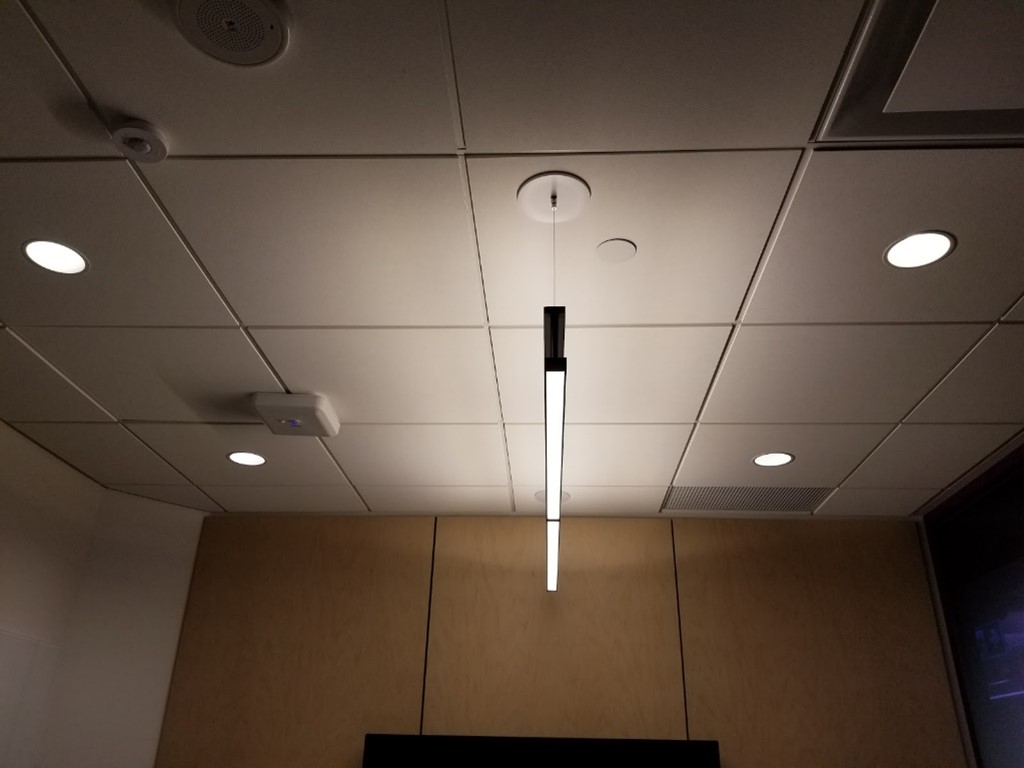
Another constraint is the placement of speakers in the physical space. For a ceiling-mounted speaker, it should be installed in the centre of a ceiling tile for aesthetic and structural purposes. Slight deviations could indicate a lack of professionalism to the client. This is a similar constraint for the Electrical team when designing lighting services, which is illustrated below.
There are also industry constraints for the number of speakers that can be connected to an amplifier. In most situations, a speaker system should only load an amplifier to 70-80% of its capacity. In other words, if a speaker system consists of 100 speakers that are each respectively rated at 0.7 Watts, the amplifier should ideally be rated for 100 Watts. This diminishes noise or distortions in the broadcasted message, and also allows for additional speakers being added in the future if need be.
Another industry design constraint is the hierarchy in which building services are prioritized. The heating, ventilation, air conditioning, plumbing, lighting, and power systems are all prioritized over the technology systems design. Therefore, due to the limited space in a ceiling, and the complex paths that are required of all the services to reach every room, the number of possible designs is very limited; each design never being ideal.
When designing systems for a building, the existence of other systems must not be forgotten. The importance of this is displayed below.
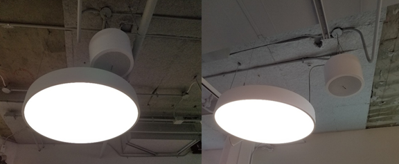
The image on the left perfectly illustrates a design company failing to conduct proper interdisciplinary coordination before issuing drawings for construction. The image on the right displays the more favourable layout, with the speaker’s cone of dispersion being left unimpeded. Simple mistakes such as these must be avoided to achieve the desired results and leave a positive lasting impression on the client.
Through the consideration of all the above design principles, requirements, and constraints, the final design for the public address system of the airport was successfully proposed and issued for construction. Although the actual drawings cannot be disclosed, the designs below attempt to depict this compliance with design principles, requirements, and constraints.
Before officially issuing drawings for construction, the design would be imported into software such as AFMG EASE (Ahnert Feistel Media Group Enhanced Acoustic Simulator for Engineers) or CATT-Acoustic (Computer-Aided Theater Technique-Acoustic) to verify the functionality of the design. A visualization of the EASE interface can be seen below.
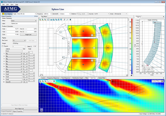
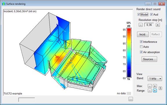
Although EASE is a very practical tool for speaker system design evaluation when determining if the SPL values will satisfy industry standards, a more sophisticated and robust software application such as CATT-Acoustic may also be required. Since STI values are more intricate and dependent on several factors that are difficult to virtually model, it's not as simple as simulating the predicted SPL values. A visualization of the CATT-Acoustic interface can be seen below.
To imitate the above software applications, a mock simulation of the speaker system coverage areas in the sample office space can be seen below. The orange zones represent excellent coverage areas, while the green zones represent good coverage areas.

For the airport, site visits were conducted to verify the compliance of audibility and intelligibility standards using electronic sound measuring devices. The airport public address system was determined to possess an STI index of 0.6, while also being acceptable in terms of audibility from all locations. For speaker spacing, it was deemed appropriate by acoustics professionals, and we successfully complied with the original budget as well.
For interdisciplinary coordination, upon three-dimensional virtual analysis through Autodesk Revit, all services within the airport were determined to be successfully coordinated. Since the office room layout was not an actual project drawing, there were no other building services to display or coordinate with. However, the speakers were placed to satisfy the aesthetic needs and typical interdisciplinary coordination needed in a project.
When considering the maximum number of speakers allowed to be connected to an amplifier, the airport was deemed by acoustics professionals to possess an appropriate number of amplifiers to satisfy overloading constraints. The way this was determined is shown below with the sample office layout’s values. The sample office layout’s speaker number constraint was effectively met with the use of 90W speakers and a 1700W amplifier.
The final public address system design of the airport was successful in satisfying all the design requirements and constraints. This compliance with all the established requirements, constraints, and standards is mimicked with the successful design of the sample office layout.
I would like to gratefully acknowledge Fernando Neto and the members of the Toronto Technology Team at the Arup Group. Their guidance, feedback, and support were pivotal in my success and accomplishments.
My experience at Arup was my very first time working in a global consultancy firm and being able to have a tangible impact on such a largely profitable project made it even more special.
Overall, my experience at Arup was beyond valuable. In four short months, I was fortunate enough to grow professionally; exercising critical thinking, learning quickly on the job, and learning about consulting, interdisciplinary coordination, project management, stakeholder management, and much more.
| AFMG | A software company responsible for the creation of EASE |
|---|---|
| Amplifier | An electronic device that can increase or decrease the number of decibels that are projected from a system of speakers. |
| Audibility | The degree to which a verbal message can be heard. |
| CATT-Acoustic | The Computer-Aided Theater Technique-Acoustic is an incredibly advanced and sophisticated software application used to simulate the behaviour of sound in different environments. |
| Cone of dispersion | The three-dimensional space in which a speaker can project sound. |
| Controller | An electronic device that allows for the management of the speaker system. |
| EASE | The Enhanced Acoustic Simulator for Engineers is a program used by designers and consultants to simulate the behaviour of sound in different environments. |
| IEC | The International Electrotechnical Commission is the governing body for standards and conformity assessment in the field of electrotechnology. |
| Intelligibility | The degree to which a verbal message can be understood. |
| Listening Plane | The height at which the intended audience’s ears will typically be. |
| NFPA | The National Fire Protection Association is responsible for the creation and maintenance of fire safety standards. |
| Noise sensor | A microphone that is capable of signalling for a sound increase or decrease to an amplifier. |
| SPL | The Sound Pressure Level is a measure of sound audibility. |
| STI | The Speech Transmission Index is a measure of sound intelligibility. |
| Telecommunications | The communication of information over cables, telephone, etc. |
"During Nick's first two weeks with us, he was unexpectedly tasked with leading a project that was clearly beyond his experience. Due to the sporadic availability of the project lead, Nick took the task, relied on the people around him for some support and guidance, and in the end he pulled it off, delivering the project complete and on-time. This type of task (leading the production of this type of work) is typically assigned to a full-time staff member. For this reason, Nick is very deserving of an outstanding rating.
During his time at Arup, Nick displayed his problem-solving mindset, communication skills, dependability, acute attention to detail, and work ethic through working long hours right from his first few weeks here to get the job done. He also showed his enthusiasm in being part of a multidisciplinary team, which made him a very fast and open-minded learner.
It has been a pleasure having Nick with us for this term. He was meticulous with his work and always delivered a high level of quality. I would recommend Nick with the highest degree to anyone in need of a good team player.